PRE35 DAC Preamplifier User Guide

CAUTION

TO REDUCE THE RISK OF FIRE, REPLACE WITH THE SAME TYPE AND RATING OF FUSE.

ATTENTION

UTILISER UN FUSIBLE DE RECHANGE MÊME TYPE.

Safety compliance

This product has been designed to meet the IEC 60065 international electrical safety standard.

CAUTION

RISK OF ELECTRIC SHOCK DO NOT OPEN

ATTENTION

RISQUE DE CHOC ELECTRIQUE NE PAS OUVRIR

The lightning flash with an arrowhead symbol within an equilateral triangle, is intended to alert the user to the presence of uninsulated ‘dangerous voltage’ within the product’s enclosure that may be of sufficient magnitude to constitute a risk of electric shock to persons.

The exclamation point within an equilateral triangle is intended to alert the user to the presence of important operating and maintenance (servicing) instructions in the literature accompanying the product.

CAUTION: To reduce the risk of electrical shock do not remove cover (or back). No user serviceable parts inside. Refer servicing to qualified service personnel.

WARNING: To reduce the risk of fire or electrical shock, do not expose this apparatus to rain or moisture.

CAUTION: In Canada and the USA, to prevent electric shock, match the wide blade of the plug to the wide slot in the socket and insert the plug fully into the socket. 

This product is designed and manufactured to meet strict quality and safety standards. However, you should be aware of the following installation and operation precautions.

1. Take heed of warnings & instructions

You should read all the safety and operating instructions before operating this appliance. Retain this handbook for future reference and adhere to all warnings in the handbook or on the appliance.

2. Water and moisture

The presence of electricity near water can be dangerous. Do not use the appliance near water – for example next to a bathtub, washbowl, kitchen sink, in a wet basement or near a swimming pool, etc.

3. Object or liquid entry

Take care that objects do not fall and liquids are not spilled into the enclosure through any openings. Liquid-filled objects such as vases should not be placed on the equipment.

4. Ventilation

Do not place the equipment on a bed, sofa, rug or similar soft surface, or in an enclosed bookcase or cabinet, since ventilation may be impeded. We recommend a minimum distance of 50mm around the sides and top of the appliance to provide adequate ventilation.

5. Heat

Locate the appliance away from naked flames or heat producing equipment such as radiators, stoves or other appliances (including other amplifiers) that produce heat.

6. Climate

The appliance has been designed for use in moderate climates.

7. Racks and stands

Only use a rack or stand that is recommended for use with audio equipment. If the equipment is on a portable rack it should be moved with great care, to avoid overturning the combination.

8. Cleaning

Unplug the unit from the mains supply before cleaning.

The case should normally only require a wipe with a soft, damp, lint-free cloth. Do not use paint thinners or other chemical solvents for cleaning.

We do not advise the use of furniture cleaning sprays or polishes as they can cause indelible white marks if the unit is subsequently wiped with a damp cloth.

9. Power sources

This appliance must be connected to a mains socket outlet using the supplied power cord. To disconnect this apparatus from power, you must disconnect the power cord. Make sure the power cord is always easily accessible.

Only connect the appliance to a power supply of the type described in the operating instructions or as marked on the appliance.

This is a Class 1 device and must be earthed.

The power switch is a single-pole switch. When the switch is in the “Off” position, the appliance is not completely disconnected from the main power.

10. Power-cord protection

Power supply cords should be routed so that they are not likely to be walked on or pinched by items placed upon or against them, paying particular attention to cords and plugs, and the point where they exit from the appliance.

11. Grounding

Ensure that the grounding means of the appliance is not defeated.

12. Power lines

Locate any outdoor antenna/aerial away from power lines.

13. Non-use periods

If the unit has a stand-by function, a small amount of current will continue to flow into the equipment in this mode. Unplug the power cord of the appliance from the outlet if left unused for a long period of time.

14. Abnormal smell

If an abnormal smell or smoke is detected from the appliance, turn the power off immediately and unplug the unit from the wall outlet. Contact your dealer immediately.

15. Servicing

You should not attempt to service the appliance beyond that described in this handbook. All other servicing should be referred to qualified service personnel.

16. Damage requiring service

The appliance should be serviced by qualified service personnel when:

A. the power-supply cord or the plug has been damaged, or

B. objects have fallen, or liquid has spilled into the appliance, or

C. the appliance has been exposed to rain, or

D. the appliance does not appear to operate normally or exhibits a marked change in performance, or

E. the appliance has been dropped or the enclosure damaged.

2.4G and 5G FCC Statements

This device complies with Part 15 of the FCC Rules. Operation is subject to the following two conditions: 

  1. This device may not cause harmful interference, and 
  2. This device must accept any interference received, including interference that may cause undesired operation. 

Cet appareil est conforme à la section 15 des réglementations de la FCC. Le fonctionnement de l’appareil est sujetaux deux conditions suivantes :

  1. cet appareil ne doit pas provoquer d’interférences néfastes, et
  2. cet appareil doit tolérer les interférences reçues, y compris celles qui risquent de provoquer un fonctionnement indésirable.

Note: This product has been tested and found to comply with the limits for a Class B digital device, pursuant to Part 15 of the FCC Rules. These limits are designed to provide reasonable protection against harmful interference in a residential installation. This product generates, uses, and can radiate radio frequency energy and, if not installed and used in accordance with the instructions, may cause harmful interference to radio communications. However, there is no guarantee that interference will not occur in a particular installation. If this product does cause harmful interference to radio or television reception, which can be determined by turning the equipment off and on, the user is encouraged to try to correct the interference by one or more of the following measures: 

  • Reorient or relocate the receiving antenna. 
  • Increase the separation between the equipment and receiver. 
  • Connect the equipment into an outlet on a circuit different from that to which the receiver is connected. 
  • Consult the dealer or an experienced radio/TV technician for help.

Please take attention that changes or modification not expressly approved by the party responsible for compliance could void the user’s authority to operate the equipment.

This equipment should be installed and operated with a minimum distance 20cm between the radiator and your body.

Cet équipement doit être installé et utilisé à une distance minimale de 20 cm entre le radiateur et votre corps.

This device complies with Industry Canada licence-exempt RSS standard(s). Operation is subject to the following two conditions: 

  1. this device may not cause interference, and
  2. this device must accept any interference, including interference that may cause undesired operation of the device.

Le présent appareil est conforme aux CNR d’Industrie Canada applicables aux appareils radioexempts de licence. L’exploitation est autorisée aux deux conditions suivantes :

  1. l’appareil ne doit pas produire de brouillage, et
  2. l’utilisateur de l’appareil doit accepter tout brouillage radioélectrique subi, même si le brouillage est susceptible d’en compromettre le fonctionnement.

Under Industry Canada regulations, this radio transmitter may only operate using an antenna of a type and maximum (or lesser) gain approved for the transmitter by Industry Canada. To reduce potential radio interference to other users, the antenna type and its gain should be so chosen that the equivalent isotropically radiated power (e.i.r.p.) is not more than that necessary for successful communication.

Conformément à la réglementation d’Industrie Canada, le présent émetteur radio peut fonctionner avec une antenne d’un type et d’un gain maximal (ou inférieur) approuvé pour l’émetteur par Industrie Canada. Dans le but de réduire les risques de brouillage radioélectrique à l’intention des autres utilisateurs, il faut choisir le type d’antenne et son gain de sorte que la puissance isotrope rayonnée équivalente (p.i.r.e.) ne dépasse pas l’intensité nécessaire à l’établissement d’une communication satisfaisante.

The CE symbol indicates that this Primare product complies with the EMC (Electromagnetic Compatibility) and LVD (Low Voltage Directive) standards of the European Community.

The WEEE symbol indicates this Primare product complies with the European Parliament and Council Directive 2002/96/EC concerning Waste Electrical and Electronic Equipment (WEEE). This product must be appropriately recycled or processed in accordance with these directives. Consult your local waste disposal authority for guidance.

The RoHS symbol indicates that Primare products are designed and manufactured to comply with the Restriction of Hazardous Substances (RoHS) as stated in the European Parliament and Council Directive 2002/95/EC.

Copyright and acknowledgments

Copyright © 2018 Primare AB.
All  rights reserved.

Primare AB
Limstensgatan 7
21616 Limhamn
Sweden

https://primare.net

Issue: PRE35DAC/2 (20/11/2018)

The information in this guide is believed to be correct as of the date of publication. However, our policy is one of continuous development and so the information is subject to change without notice, and does not represent a commitment on the part of Primare  AB.

Primare is a trademark of Primare AB. 

This guide was produced by
Human-Computer Interface Ltd.
http://www.interface.co.uk
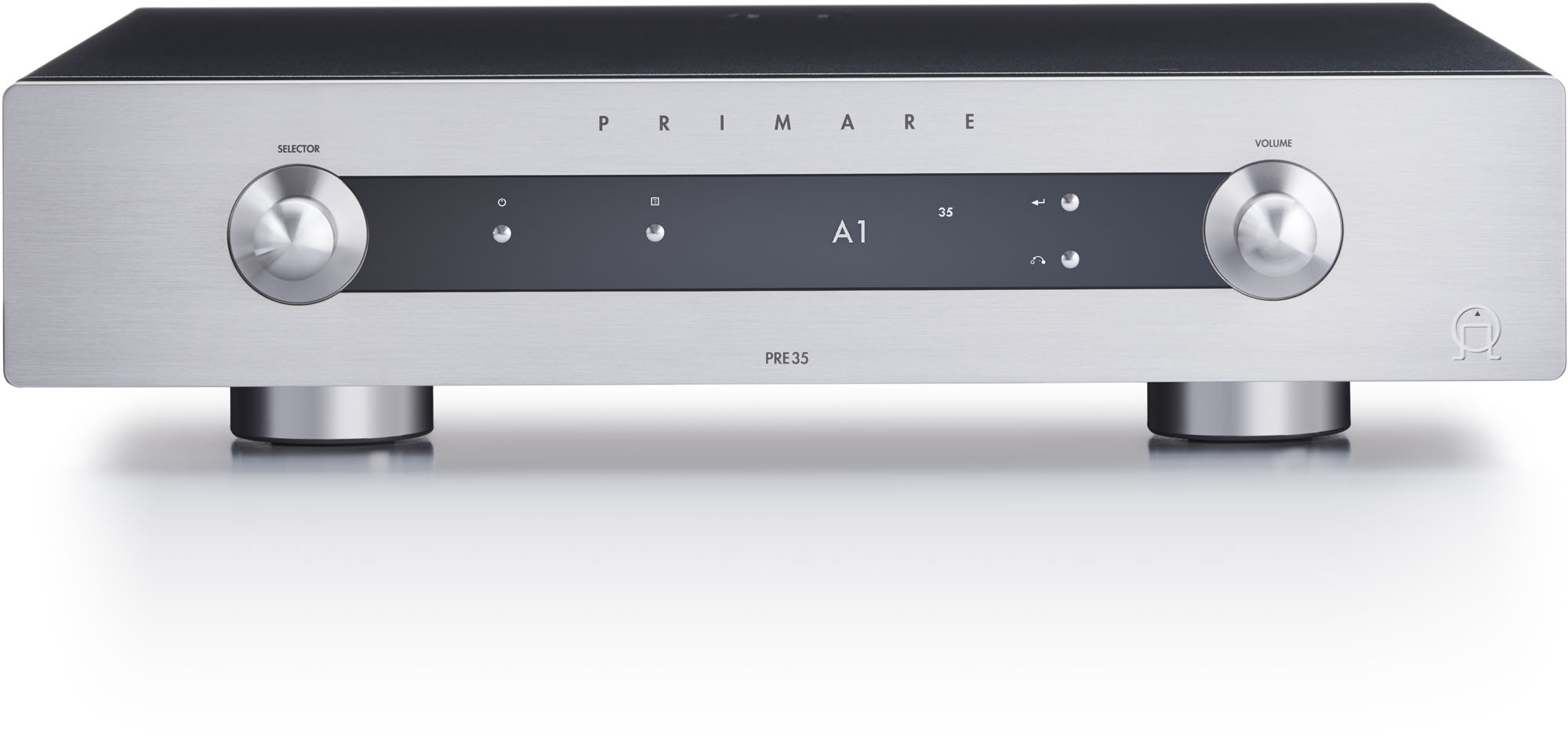
Congratulations on selecting your new PRE35 DAC Preamplifier

This user guide describes the features and explains how to set up the preamplifier for the best sound quality and ease of operation in order to allow for the most enjoyable reproduction of sound from all your sources.

For additional support and assistance please contact your local authorized Primare dealer, or visit our website at www.primare.net

3.1. Unpack the PRE35

Your PRE35 is supplied with:

  • Mains cable
  • Trigger cable
  • C25 remote control with batteries
  • AC Polarity Pen

If any of these items are missing please contact your supplier. We recommend you retain the packaging in case you need to transport the unit at a later date.

Note that the PRE35 is supplied with a protective film on the display glass. Remove the film for a clearer whiter display.

3.2. Connect to a power amplifier

The PRE35 is designed to be connected to a power amplifier with either balanced or unbalanced inputs.

If the power amplifier provides balanced inputs, such as the Primare A35.2:

  • Connect the PRE2 or PRE3 L and R outputs from the PRE35 to the L and R balanced inputs in the power amplifier, using high quality XLR cables.

If the power amplifier only provides unbalanced inputs:

  • Connect the PRE1 L and R outputs from the PRE35 to the L and R inputs on the power amplifier, using high quality RCA cables.

Fixed-level analogue output

The PRE35 also provides a fixed-level analogue output on the LINE output on RCA connectors, to allow you to connect to active speakers or an analogue recorder.

Digital output

The PRE35 also provides a coax digital output on an RCA connector.

3.3. Connect inputs

You can connect up to two balanced sources, up to three unbalanced sources, and up to six digital sources to the inputs on the back panel.

Balanced inputs

  • Connect balanced sources, such as the Primare CD35 CD player, to balanced inputs A1 and A2 using high quality XLR cables.

Unbalanced inputs

  • Connect unbalanced sources to the unbalanced inputs A3, A4, and A5 using high quality RCA cables.

Digital inputs

  • Connect digital optical sources to the digital optical inputs D6 to D9 using optical cables.
  • Connect digital coax sources to the digital coax inputs D10 and D11 using digital RCA cables.

You can also connect a PC or Mac to the USB-B input to use the PRE35 as an audio output device for your computer.

3.4. Connect power

  • Plug one end of the mains cable supplied with the PRE35 into the power connector on the back panel, and connect the other end to a wall socket.

If this cable is not suitable for your power outlets please contact your supplier for an alternative cable.

Note: See Phase for information about getting the best sound from your PRE35.

WARNING: Always disconnect the PRE35 from the mains power before connecting or disconnecting any cables.

  • Switch on the PRE35, using the switch on the back panel.

To switch on from standby

  • Press on the front panel or remote control.

The display shows:

3.5. Back-panel connections

The following diagram explains the function of each of the connectors on the back panel:

Selecting PRE35 mode

The remote control can operate any associated Primare products you have in your system.

To make the remote control operate the PRE35

  • Press the AMP AV button once.

To make the remote control operate another product

  • Press the AMP AV, CD SC, or PRE AUX button as appropriate.

Press once to select the product on the top line of the button, or twice to select the product on the second line.

The indicators at the top of the remote control light when pressing a button to show which mode the remote control is in.

Fitting the batteries

Before using the remote control you need to insert the two AAA cells supplied with the C25.

  • Open the cover on the back of the remote control by pressing the back cover gently near the centre of the remote control, and sliding it towards the edge of the remote control.
  • Insert the two batteries, with the polarity as indicated on the bottom of the battery compartment.
  • Replace the cover and push until it clips into place.

Note: Replace only with 1.5V alkaline cells type AAA or equivalent.

When disposing of old batteries please be considerate to the environment.

5.1. Front panel controls

Selector

Selects an input. In the settings menus navigates between settings.

Standby

Switches the PRE35 to standby, or switches it on from standby.

Menu

Displays the settings menus or exits from the menus.

Select

In the settings menus selects a setting or saves an edited setting.

Back  

In the settings menus navigates back or cancels editing a setting.

Volume

Changes the volume.

5.2. Changing the volume

The PRE35 allows you to vary the volume from 0 (silence) to 99 (maximum).

To change the volume

  • Rotate the VOLUME control on the front panel, or press the + or buttons or the  or  buttons on the remote control.

The current volume setting is shown on the front panel; for example:

5.3. Selecting a source

The PRE35 provides a choice of 12 inputs. Initially these are labelled as shown in the following table, but you can give them your own aliases to suit the sources in your system; see Alias.

Label Description
A1, A2 Balanced analogue on XLR connectors.
A3–A5 Unbalanced analogue on RCA connectors.
D6–D9 Digital optical on TOS connectors.
D10, D11 Digital coax on RCA connectors.
PC/MAC (12) Digital on USB-B connector.

To select a source

  • Turn the SELECTOR until the source is indicated on the front panel display; for example:

    Alternatively, press the or buttons on the remote control to step between sources, or press one of the buttons 1 to 12 on the remote control to select the corresponding source directly.

    5.4. Changing the display brightness

    To change the front panel display brightness

    • Press the DIM button on the remote control to step through the three levels of illumination and blank.

    If you turn the display off it will be restored briefly when you operate any control.

    The display automatically dims after ten minutes; you can adjust this delay in the settings menus; see General settings.

    To play music from a source

    • Connect the source via a suitable cable:
    Source Cable
    Balanced analogue XLR cable
    Unbalanced analogue Phono RCA cable
    Digital optical Digital optical cable
    Digital Digital coax cable
    • Select the source from the front panel, or using the remote control.

    To use the PRE35 as a PC/Mac sound output device

    • Connect the Mac or PC to the PRE35 via a USB-A to USB‑B cable.

    PC

    Windows 7, 8, 8.1, or 10 (32/64-bit) is required. You need to install the Primare xmos audio driver, available on primare.net.

    Macintosh

    OSX 10.4 or later is recommended. No driver is required.

    • Connect the computer’s USB port to the USB B input on the PRE35 using a USB A to USB B cable. 

    The PRE35 will then appear as a sound output device called Primare USB Audio DAC in the Sound control panel (PC) or Sound system preferences panel (Macintosh).

    • Select the PC/MAC source on the PRE35.
    • Select the Primare USB Audio DAC as the sound output device in the Mac Sound system preferences panel or the PC Sound control panel.

    7.1. Using the settings menus

    You can view and change the PRE35 settings from the front panel or remote control.

    To display the settings menu

    • Press the  button on the front panel, or the MENU button on the remote control.

    The settings menu is displayed:

    To step between settings

    • Turn the SELECTOR control on the front panel, or press the  or  buttons on the remote control.

    The current setting is shown highlighted.

    To change a setting

    • Press the  button on the front panel, or the SELECT button on the remote control.

    The current value is shown highlighted.

    • Turn the SELECTOR control on the front panel, or press the  or  buttons on the remote control, to change the value of the setting.

    As you change it the new value is shown in the menu.

    • Press the  button on the front panel, or the SELECT button on the remote control, to save the value you have set.

    To navigate back or cancel editing a setting

    • Press the button on the front panel or remote control.

    To exit from the settings menu

    • Press the  button on the front panel, or the MENU button on the remote control.

    7.2. INPUT SETTINGS

    The INPUT SETTINGS menu allows you to customise the inputs to suit the sources in your system:


    INPUT

    Initially the INPUT SETTINGS shows the settings for the currently selected input. Alternatively the INPUT option allows you to step between all the inputs. The subsequent options will change according to the input.

    ALIAS

    Allows you to give the source a name; eg RADIO.

    • Highlight the ALIAS item, then press the SELECT button on the remote control.

    The RENAME INPUT menu is displayed:

    • Turn the SELECTOR control on the front panel, or press the  or buttons on the remote control, to select the first letter.
    • Press the  button on the front panel, or the SELECT button on the remote control, to select it.

    After adding each character you have the options:

    ADD NEW CHARACTER
    CONFIRM ‘A’
    CLEAR ALIAS

    where CONFIRM shows the alias you have entered so far.

    • Select ADD NEW CHARACTER to add the remaining letters, up to a maximum of six characters.
    • Select CONFIRM when you have entered the alias you want.

    STATUS

    Choose between ENABLED (default) or DISABLED to specify whether the input is enabled.

    AUTO SENSE

    Choose between: SELECT to automatically select an input containing an audio signal if the PRE35 is on; WAKE+SELECT to automatically wake up the PRE35 from standby, if necessary, and select an input containing an audio signal; and OFF (default) to disable automatic switching.

    VOLUME

    Choose between VARIABLE (default) or FIXED to specify whether the input should have variable or fixed gain.

    FIXED is 0dB gain, equivalent to volume setting 66, and will overrule MAXIMUM VOLUME in AUDIO SETTINGS.

    Selecting FIXED will show a loud-volume warning. Select YES to proceed or NO to cancel the fixed gain setting.

    Fixed gain functions as an SSP (Surround Sound Pass-through) allowing the PRE35 to be used as an amplifier in a multi-channel system setup

    INPUT GAIN

    Choose between: -30dB to -1dB, 0dB (default), or +1dB to +30dB to set the gain for the selected input.

    If the gain is set too high on an input clipping may occur, and the message:

    DECREASE INPUT GAIN

    will be displayed. In this case reduce the gain until the warning message is not displayed.

    7.3. AUDIO SETTINGS

    The AUDIO SETTINGS menu allows you to customise the balance and start-up volume, and the maximum and mute volume.

    BALANCE

    Allows you to adjust the balance between 00LR-9 (far left), 00LR00 (centred, default) and -9LR00 (far right).

    DEFAULT VOLUME

    This setting determines the default output volume of your PRE35.

    Select LAST USED to use the last used volume prior entering standby, or select SPECIFIED to set a specific volume.

    Default setting is “SPECIFIED” with volume 20.

    MAXIMUM VOLUME

    Sets the maximum volume limit between 0 and 99. The default is 99.

    MUTE VOLUME

    Sets the volume when unit is muted. You can choose between 0 (default) and 30.

    If the current volume is lower than the specified MUTE VOLUME, the volume will be set to 0 when pressing mute.

    ANALOG-DIGITAL OUT (DM35 ONLY)

    Allows you to choose the sample rate for analogue inputs on the digital output as 96kHz (default) or 48kHz. For digital inputs the output format is the same as the input.

    PCM UPSAMPLING (DM36 ONLY)

    Upsampling of 44.1/48 kHz PCM audio to 88.2/96 kHz is enabled by default.

    If upsampling is not preferred, disable this option.
    Note: disabling PCM upsampling could cause a silent gap in the beginning of a song during MQA playback.

    SPEAKER MUTE (WiSA ONLY)

    This setting allows you to mute the speaker output of PRE35, while leaving the analog RCA and XLR outputs active. This allows for headphone listening using a headphone amplifier connected to the RCA/XLR outputs with the WiSA speakers muted. Additionally, LINE output can be selected when volume is controlled at the headphone amp or PRE output when you want to control volume from PRE35.

    Choose between OFF (default) to leave SPEAKER MUTE deactivated, or ON to activate SPEAKER MUTE. When activated, the letters “SM” will be shown in front of the current volume in OLED display. When deactivated, “SM” will disappear and volume will return to DEFAULT VOLUME setting.

    Press and hold the MUTE button on C25 remote control to toggle the SPEAKER MUTE setting.

    7.4. GENERAL SETTINGS

    The GENERAL SETTINGS menu allows you to configure the general operation of the PRE35:

    SHOW INPUTS

    Choose between ALL (default), to show all inputs, or WITH SIGNAL, to show only inputs that have a signal.

    FRONT PANEL

    Choose LOCKED to lock the front panel buttons and knobs, or UNLOCKED (default) to use them.

    To unlock the front panel buttons use the remote control to select this menu, or remove power from the PRE35 for a few seconds.

    AUTO-DIM

    Allows you to choose the delay for dimming the display after no user interaction, between: AFTER 1MIN, AFTER 5MIN, AFTER 10MIN (default), or OFF.

    LED BRIGHTNESS

    Displays the LED BRIGHTNESS menu to allow you to set the display brightness to between 1 and 5 for each display dimming level:

    DIM HIGH (default 3), DIM MID (default 2), DIM LOW (default 1), or DIM OFF (default 1).

    STANDBY SETTINGS

    Displays the STANDBY SETTINGS menu to allow you to specify the standby settings.

    STANDBY MODE can be set to ECO to reduce the standby consumption to less than 0.5W, but only allows the PRE35 to wake from the analogue and digital inputs, or NORMAL which also allows the PRE35 to wake from the PC/MAC input.

    AUTO-STANDBY automatically switches the PRE35 to standby if there is no user interaction or audio from the current source for a specified delay: AFTER 10MIN, AFTER 15MIN, AFTER 20MIN (default), or OFF.

    FACTORY RESET

    Resets the PRE35 to the factory default settings.

    You are prompted to confirm. Select YES to proceed or NO to cancel.

    FIRMWARE VERSIONS

    Displays the FIRMWARE VERSIONS menu to allow you to view the versions of firmware installed.

    8.1. Introduction

    WiSA, which stands for Wireless Speaker and Audio, is an audio standard that wirelessly transmits multichannel, high-definition audio to loudspeakers. It supports up to eight channels of uncompressed digital audio at 96kHz, 24bit resolution.

    The PRE35 includes built-in support for WiSA, allowing you to deliver a stereo audio signal to loudspeakers without the need for the usual loudspeaker cables.

    The audio is transmitted using the license-free 5 GHz band, and it avoids interference by using dynamic frequency selection (DFS) to change channels when necessary.

    This page describes how to set up WiSA speakers for use with the PRE35 using either the settings menus, or the Primare App.

    Communication

    The communication between the PRE35 and WiSA speakers is at 96kHz, 24 bits. Other sample rates up to and including 192kHz are converted to 96kHz. WiSA can only convert sample rates up to 192kHz 24bit. Sample rates above 192kHz will be silent on WiSA, but audible on the analogue RCA output.

    WiSA does not support DSD format, so it is converted to PCM before being output; however, DSD format from the USB-B PC/MAC input will be silent on WiSA speakers, but audible on the analogue RCA output.

    Speaker types

    WiSA speakers can be labelled in the WiSA software, and sometimes on the physical speaker itself, with one of the labels: FR (front right), C (centre), FL (front left), SR (surround right), SL (surround left), SBR (surround back right), SBL (surround back left), or SUB (subwoofer).

    Unlabelled speakers are not preprogrammed to any channel and need to be assigned to a channel.

    In the PRE35 a speaker labelled as FR will pair as Right (R), a speaker labelled as SUB will pair as Sub (S), and all other speakers including unlabelled speakers will pair as Left (L). You can change these pairings as described below.

    8.2. Switching on

    If the WiSA module is ON in the Speaker Settings menu the WiSA module will always start up when you turn the PRE35 on, and the display will show:

     
    WiSA Initiating
    Please wait…
     

    It will then connect to the associated speakers. The display will show if your unit was unable to find any of your previously associated speakers.

    WiSA will be shown in the display once the WiSA module is on and has found and connected to WiSA speakers.

    8.3. Setting up WiSA from the settings menu

    We recommend that you connect your WiSA speakers before you do the PRE35 setup.

    To set up one R and one L speaker

    If you have one speaker labelled FL and one labelled FR they will be associated correctly automatically with the following procedure:

    • Make sure all your speakers are turned on and in associate mode, usually indicated by a flashing light on the speaker.
    • Press and hold the SPS (Speaker Pairing System) button on the back panel of the PRE35 for three seconds.

    The display will show:

    Scanning for WiSA speakers

    This will turn on the WiSA module and add all available WiSA speakers.

    It will then show a notification of all the speakers it found:

    1 R output is associated 
    1 L output is associated


    Your speakers are now set up to the PRE35 and ready to play.

    To set up two unlabelled speakers

    If you have two unlabelled speakers they will both pair as L speakers. You then need to change the association of the Right speaker as follows:

    • Make sure only the speaker you want to use as the Right speaker is turned on and in associate mode, usually indicated by a flashing light on the speaker.
    • Press and hold the SPS (Speaker Pairing System) button on the back panel of the PRE35 for three seconds.

    The display will show:

    Scanning for WiSA speakers

    It will then show a notification of all the speakers it found:

    0 R output is associated 
    1 L output is associated


    • Go to the option ASSOCIATED WISA SPEAKERS in the WISA SETTINGS menu and change the associated speaker to Right.
    • Turn on the speaker you want to use as the Left speaker and make sure it is in associate mode, usually indicated by a flashing light on the speaker.
    • Select the ADD SPEAKER option in the WISA SETTINGS menu.

    The notification should now show the additional entry:

    1 R output is associated 
    1 L output is associated


    Your speakers are now set up to the PRE35 and ready to play.

    To set up 2-way speakers

    Some makes of speakers, called “2-way speakers”, will appear as two WiSA devices per speaker:

    2 R output is associated 
    2 L output is associated


    • Identify which of the two devices should play as Right and configure them appropriately.
    • Likewise, identify which of the two devices should play as Left and and configure them appropriately.

    Your speakers are now set up to the PRE35 and ready to play.

    8.4. Setting up WiSA using the Primare App

    You can also set up your WiSA speakers using the Primare App. We recommend that you connect your WiSA speakers before you do the PRE35 setup.

    • Select the SETTINGS panel.
    • Expand the Speaker settings section of the menu.
    • Select the WiSA Settings option.

    The WiSA settings screen is displayed:

    The following options are available:

    Option Description
    WiSA module Enables or disables the WiSA module.
    WiSA network Enables or disables the WiSA network.
    Add WiSA speakers Allows you to add speakers to your WiSA network.
    Dismiss WiSA speakers Removes all associated speakers from your WiSA network.
    WiSA speaker configuration Allows you to change speaker positions, subwoofer polarity, levels, crossover, and distance.

    To enable or disable the WiSA module or network

    • Press WiSA module or WiSA network if you want to disable or enable the module and/or network.

    To add or remove WiSA speakers

    • Press Add WiSA speakers or Dismiss WiSA speakers to add or remove speakers from your configuration.
    • To dismiss a single speaker press Dismiss speaker when configuring the speaker.

    To configure the WiSA speakers

    • Press WiSA speaker configuration to configure the speakers in your configuration.

    The following instructions are displayed:

    The following screen then represents each of the speakers in your configuration:

    To identify each speaker

    • Press and hold the speaker symbol; a sound will be played through that speaker to identify it.

    To change the position of a speaker

    • Drag the speaker’s icon and drop it into the new position.

    For example, you can move the Right speaker and position it in the Left position.

    To adjust the speaker levels

    • Press the Speaker levels button.
    • Press the head icon at the listening position, and then select the speaker you want to adjust:

    Noise will be produced from that speaker.

    • Adjust the level with + and buttons.
    • Press Finished to save the changes when you’ve finished.

    To configure the subwoofer

    If you have a subwoofer in your system, click its icon on the WiSA configuration screen.

    The following screen lets you set the low pass filter, distance, and polarity:

    • Press Lowpass to select the low pass filter from a pop-up menu.
    • Press Distance to set the distance from the listening position to the speaker, in metres:

    • Press Polarity to set the polarity, choosing the setting that produces the best sound.
    • Press Finished to save the changes when you’ve finished.

    8.5. Troubleshooting

    WiSA module does not start up.

    • Go to WISA SETTINGS in the GENERAL SETTINGS menu and make sure the WiSA module is on.

    Unable to connect to speakers

    • Make sure your speakers are WiSA certified.
    • Make sure your speakers are connected to power.
    • Make sure your speakers are in associate mode.
    • Select ADD SPEAKERS.

    If above does not help and you are unable to find any speaker please contact a Primare store for service support.

    If your device finds some but not all of the speakers

    Please contact you speaker manufacturer for support.

    Speakers are very quiet

    If you feel that you need to turn up the volume a lot for your speaker to output any sound, your speaker may be missing WiSA certified firmware. Please contact your speaker manufacturer for support.

    No sound from associated speakers

    • Make sure the speaker is associated to your device.
    • Make sure your Primare device is not muted
    • Make sure WISA MODULE is set to ON and WISA NETWORK is set to ON.
    • Make sure the ANALOG OUTPUT setting is set to PRE (LINE mutes the WiSA output).
    • Make sure the SPEAKER MUTE setting is set to OFF (ON mutes the WiSA output).

    If there is still no sound out:

    • Make sure that your Primare device outputs sound both on analog and digital out.

    Please note that when playing on the PC/MAC input, if you play a sample rate above 192kHz the sound will not be output on WiSA.

    If there is no sound from the digital output please contact your local Primare store for service support.

    Product is stuck in “WiSA initiating please wait…”

    Please contact your local Primare store for service support.

    To move a loudspeaker between WiSA networks

    • Dismiss the speaker from the WiSA network, and then add it to the second network.

    Analogue inputs

    Balanced inputs

    2 x XLR, 30kΩ impedance

    Unbalanced inputs

    3 x RCA, 15kΩ impedance

    Analogue outputs

    Preamplifier output

    2x XLR, 380Ω impedance

    1 x RCA, 100Ω impedance

    Line output

    1 x RCA, 100Ω impedance

    Digital inputs

    4 x Optical/TOSLINK 192kHz/24 bit

    2 x RCA 192kHz/24 bit

    1 x USB-A up to 192kHz/24 bit; up to DSD128 (5.6MHz)

    1 x USB-B up to 768kHz/32 bit; up to DSD256 (11.2MHz)

    Digital output

    1 x RCA

    Analogue input = selectable between 48 or 96kHz

    Digital input = native output

    Wireless output

    1x Wireless stereo output using WiSA® technology

    Performance

    Gain

    Preamplifier output: 16.5dB

    Line output: 0dB

    Speaker output: 42.5dB

    Analogue frequency response

    20Hz – 20kHz: ±0.1dB

    Distortion

    THD + N: < 0.002%, 20Hz – 20kHz

    Signal to noise

    >100dB (AES17 filter)

    General

    Control

    C25 system remote control
    RS232
    IR in/out
    Trigger out

    Power Consumption

    Standby : < 0.3 W
    Operating: 33 W < 50 W

    Dimensions

    430 x 420 x 106 mm (w x d x h) with knobs and connectors

    430 x 382 x 106 mm (w x d x h) without knobs and connectors

    Weight

    11 kg

    Colour

    Black or titanium

    These instructions help you get the best possible sound from your PRE35.

    Phase

    The phase of the AC supply can make a significant difference to the sound.

    Use the Polarity Pen supplied with the PRE35 to verify which pin is live on your AC power cable.

    Ensure that the live pin of the AC power cable is connected to the left-hand pin of the power connector, viewed from the back panel:

    Burn-in

    Your Primare will start to sound best after an initial burn-in of approximately 24 hours. 

    You will notice a further smaller improvement in sound quality for at least another 3 days’ playing.

    RS232 and trigger

    The RS232 input allows you to connect the PRE35 to a controller system. Use a twisted (null modem) cable. For more information contact Primare at info@primare.net or visit www.primare.net.

    The Trigger output allows the PRE35 to switch on other devices, such as a CD32.

    Using the PRE35 with a CD35

    Your PRE35 is an ideal companion to the Primare CD35 CD Transport. For best results link the two products together as follows using the two cables supplied with the PRE35:

    To connect the trigger cable

    The Trigger cable ensures that the CD35 switches on, or to standby, when you operate the  button on the front panel of the PRE35.

    • Connect the Trigger cable from the PRE35 TRIG OUT to the CD35 TRIG IN.

    Error messages

    The following error messages on the front panel display indicate an error condition:

    DECREASE INPUT GAIN

    Clipping has occurred on an input. Decrease the input gain; see Input gain.

    DC ERROR

    Try the following

    • Power off PRE35 and disconnect the speaker connections.

    If this solves the problem, check the speaker wiring.

    If the problem persists

    • Power off PRE35 and disconnect all input connections.

    If this solves the problem, there is a DC offset on one of the inputs.

    If the problem persists

    • Contact your dealer for service arrangements.

    Factory reset

    Press and hold the standby button on the front panel to display the main firmware version number.

    Press and hold the standby button on the front panel for 10 seconds to perform a factory reset of the PRE35.

    You can also do a factory reset from the Prisma app, or from the the standby button menu; see General settings.

    Translate

    You can use Google Translate to translate the contents of the Primare website. To do that, select the language you would like to translate into in the list below.

    Please bear in mind, since the Google Translate is an automatically generated translation, we do not take any responsibility for errors in the text.